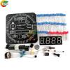
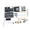
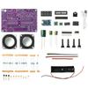
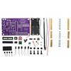
Quantity : 1
High-concerned chemical : none
Package : SOP
is_d : Yes
Supply Voltage : 3.7V
Application : Speaker
Type : Module
Brand Name : DIY NOW
Origin : Mainland China
Condition : New
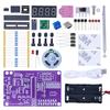
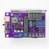
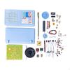
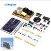
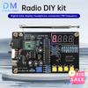
Name : FM radio production kit
Control chip : RDA5807 8002D (STC81K17 digital display version)
Power supply : 3 AA batteries, 3.7V lithium battery, please bring
Speaker : 1.5-inch 4 ohm 3W speaker (outer diameter 40mm)
Search range : 50-108 MHz
Signal-to-noise ratio : >60dB
Sensitivity : <10uV
Frequency response : 150Hz-20KHz
Features:
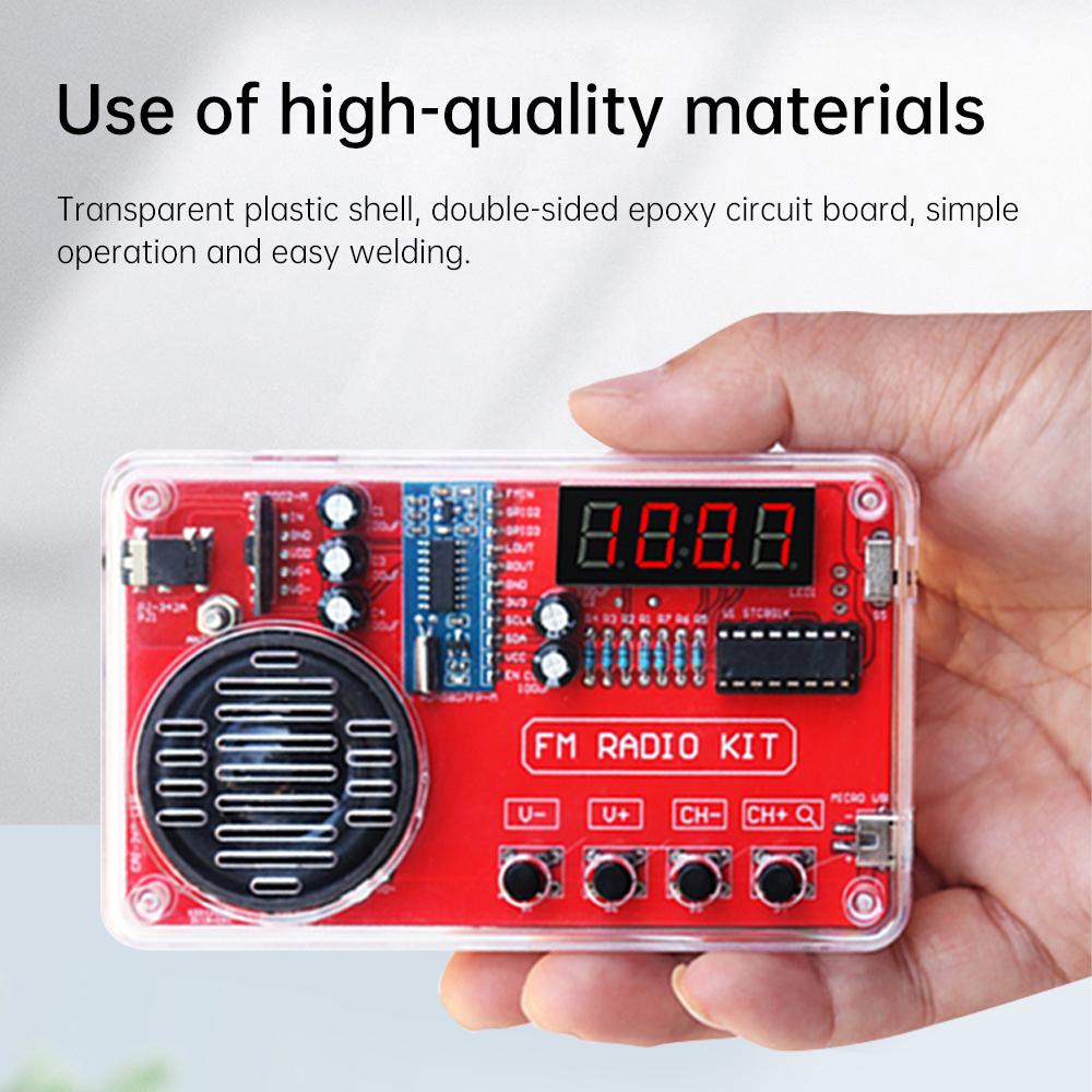
1. Made of high-quality materials, with a transparent plastic casing and double-sided epoxy circuit board, easy to operate and solder.
2. Equipped with a radio module, offering advantages such as noise cancellation, bass enhancement, high sensitivity, low noise, and strong anti-interference ability.
3. Button control for adjusting volume, switching channels, clearing all channels, and rescanning and saving stations.
4. Multiple specifications available: simple version without digital display, version with digital display, and version with digital display and charging module, available as needed.
5. Wide range of applications, suitable for school teaching, hobby development, scientific research, and DIY enthusiasts.
Product Parameters:
Material: Transparent plastic casing, double-sided epoxy circuit board
Name: FM Radio Making Kit
Control Chip: RDA5807 8002D (STC81K17 digital display version)
Power Supply: 3 AAA batteries, 3.7V lithium battery (not included)
Speaker: 1.5-inch 4-ohm 3W speaker (outer diameter 40mm)
Tuning Range: 50-108 MHz
Signal-to-Noise Ratio: >60dB
Sensitivity: <10uV
Frequency Response: 150Hz-20KHz
Product Size: 115*70*28mm
Differences:
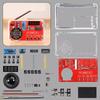
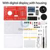
1. Digital Display Version Kit - with Casing: A kit with a casing is shipped, which can display the radio frequency. Requires 3 AAA batteries (not included).
2. Simple Version Kit - with Casing: A kit with a casing is shipped, which cannot display the radio frequency. Requires 3 AAA batteries (not included).
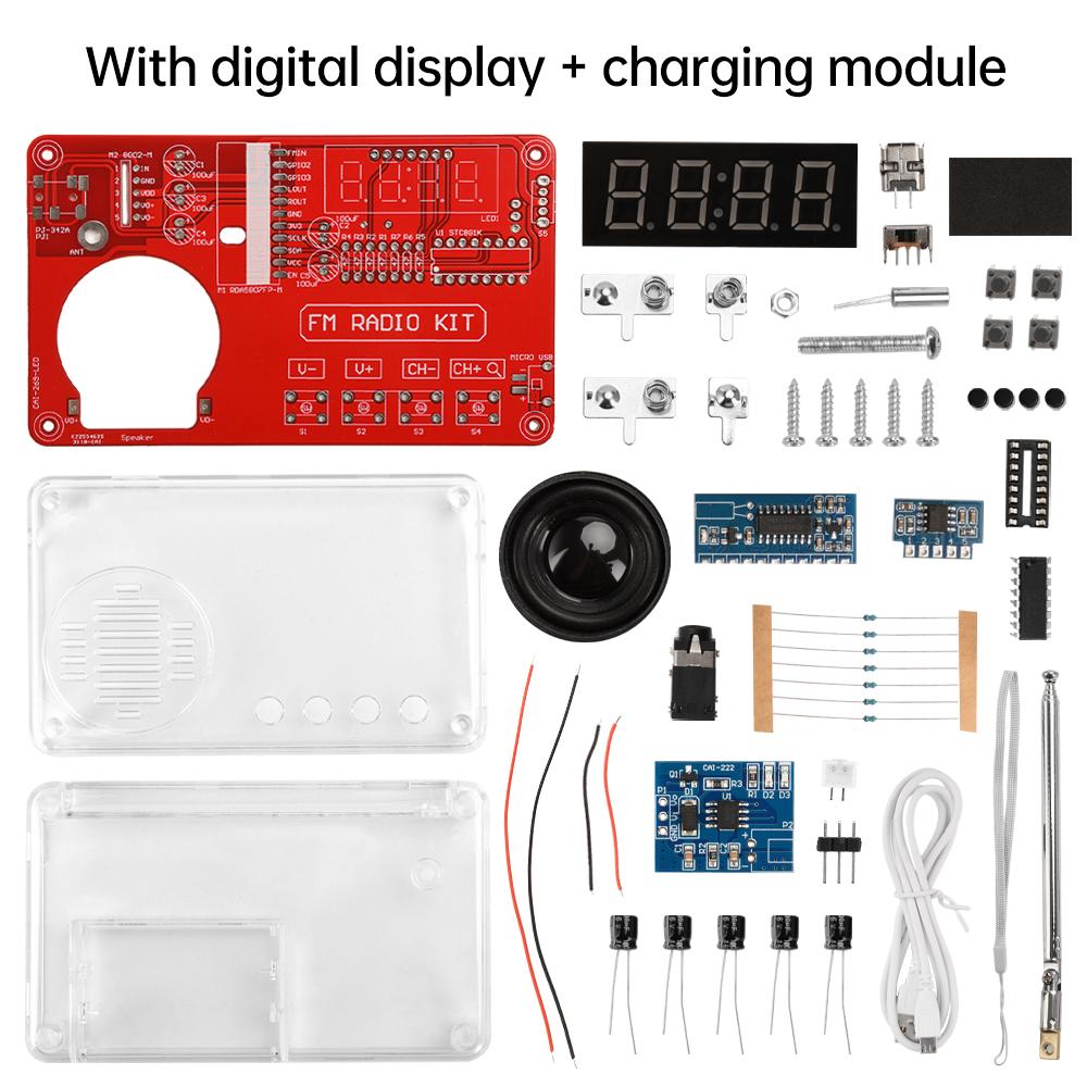
3. Digital Display Version Kit - with Casing and Charging Module: A kit with a casing is shipped, including a charging module, charging cable, and lanyard. A lithium battery can be added by the user. It can display the radio frequency. Requires a lithium battery or 3 AAA batteries (not included).
Instructions for Use:
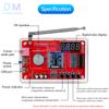
1. Power Supply: Push the switch up for battery power; push down for MICRO USB power. 2. After powering on, the indicator light will illuminate and a rustling sound will be heard. Then you can extend the antenna and tune the radio. [If the indicator light is on but there is no sound, you can power off, wait about half a minute, and then power on again.]
3. Channel Selection: Press CH+ to select the next channel, and press CH- to select the previous channel. [Channel selection also involves searching for stations; please be patient.]
4. Volume Adjustment: Press V- to decrease the volume, and press V+ to increase the volume.
5. Headphone Use: Insert the headphone plug into the headphone jack, and the sound will play through the headphones. [Headphones are not included in the kit.]
6. When searching for stations and using the radio, extend the antenna and find a suitable direction. In areas with many buildings or in remote mountainous areas, there may be fewer radio stations or no stations may be found.
Soldering Method:
1. Solder Wire Requirements: Diameter 0.8-1mm, melting point around 183 degrees Celsius. Please do not use high-melting-point solder.
2. Soldering Iron Requirements: 30-40W
3. Keep the soldering iron tip clean: A layer of black impurities formed by oxidation on the surface of the soldering iron tip forms a heat insulation layer, causing the soldering iron tip to lose its heating function.
4. Soldering Steps are shown in the diagram below: For general solder joints, soldering takes approximately 2-3 seconds.
Please strictly follow the soldering requirements.
1. Please check the quantity and model of the components first. Measure as many components as possible with a multimeter.
2. Install according to the tutorial steps.
3. When installing, install the shorter components first, then the taller components.
4. After installing a part of the components, solder them, and trim the component leads promptly.
5. When soldering, pay attention to the soldering temperature; it should not be too high, and the soldering time should not be too long, otherwise, it will damage the circuit board or components.
6. After soldering, check again whether the solder joints are qualified and whether the components are installed incorrectly.
7. When powering on for testing, ensure that the positive and negative terminals of the power supply are not reversed. The voltage should not exceed 3V.
8. When fixing the casing with screws, tighten the screws only enough; do not overtighten them. 9. If a malfunction occurs, first check if the power supply is correct, then check the component installation and solder joints.
Radio tutorial: http://www.diyleyuan.com/JC/2690.html
Product list:
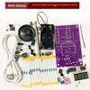
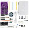
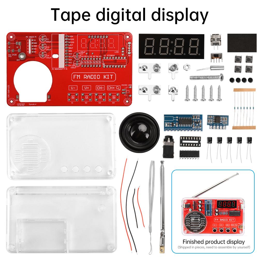
1 x Radio kit (DIY kit, requires customer to solder it themselves.)
difference:
1. Digital display spare parts - with shell: A set of spare parts with shell is shipped, which can display the radio frequency and requires 3 batteries with size 7 for power supply.
2. Simplified version of loose parts - with shell: A set of loose parts with shell is shipped, which cannot display the radio frequency and requires 3 batteries of size 7 to be provided for power supply.
3. Digital Edition Parts with Shell Charging Module: A set of parts with shell is shipped, equipped with charging module, charging wire, hanging rope, and can be equipped with lithium battery. It can display radio frequency and requires self provided lithium battery or 3 No. 7 batteries.
instructions
1. Power supply: Pull up the battery for power supply; Pull down to connect MICRO USB power supply.
2. After power on, the indicator light will light up and there will be a rustling sound, and then you can open the antenna and adjust the station. If the indicator light is on and there is no sound, you can turn off the power and wait for about half a minute before turning it back on
3. Channel selection: Press CH+to select the next channel, press CH - to select the previous channel. [Selecting channels while searching for channels, patience is required]
4. Volume adjustment: Press V - to decrease the volume, press V+to increase the volume.
5. The use of headphones: Insert the headphone jack into the headphone jack, and the sound will be played from the headphones. [The kit does not come with headphones]
6. When searching for and using radio stations, the antenna should be stretched to find a suitable direction. In areas with many buildings or remote mountainous areas, radio stations may be scarce or not searchable.
Welding method:
1. Solder wire selection requirements: diameter 0.8-1mm, melting point around 183 degrees, please do not use high melting point solder.
2. Selection requirements for circuit iron: 30-40W
3. Keep the soldering iron tip clean: A layer of black impurities oxidized on the surface of the soldering iron tip forms a thermal insulation layer, causing the soldering iron tip to lose its heating effect.
4. The welding steps are shown in the following figure: for general welding points, it takes about 2-3 seconds to complete the welding.
Please strictly follow the welding requirements for welding.
1. Please check the quantity and model of the accessories first. Try to measure with a multimeter if possible.
2. Follow the tutorial steps to install.
3. When installing, install the short components first and then the high components.
4. Install a portion of the components, solder a portion of the components, and promptly cut off the component pins.
5. When welding, pay attention to the welding temperature not being too high and the welding time not being too long, otherwise it may damage the circuit board or components.
6. After welding, check again whether the welding points are qualified and whether the components are installed incorrectly.
7. When conducting power on debugging, be careful not to reverse the polarity of the power supply. The voltage cannot exceed 3V.
8. When fixing the shell with screws, pay attention to tightening the screws and do not overtighten them.
9. If there is a malfunction, first check whether the power supply is correct, and then check the component installation and solder joints
Package include:
1X radio kit (DIY loose parts shipped, customers need to weld it themselves.)
label:yes
Power: 10 W








 Vrácení peněz při nedoručení